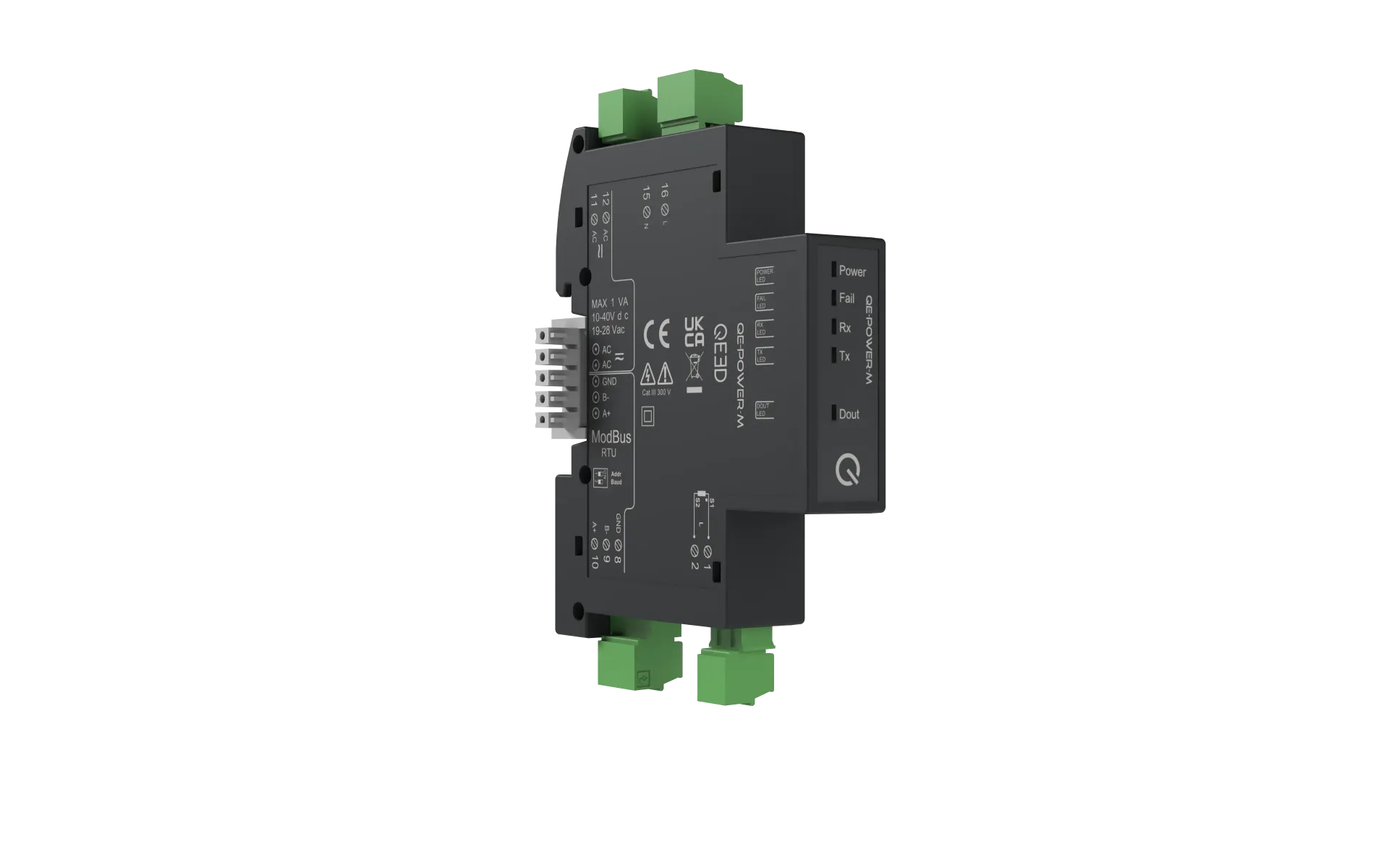
MONOPHASE NETWORK ANALYSER - 17.5 mm
QE-POWER-T - Technische specificaties
Accuracy (@25°C, 50 Hz)
| Parameter | Value |
| ELECTRICAL PROPERTIES | |
| Power supply | 10÷40 VDC or 20÷28 VAC @ 50/60 Hz |
| Power consumption | 1.2
W max 2 VA max |
| Isolation | 4
kVrms between power supply and measurement inputs 4 kVrms between RS485 and measurement inputs 1.5 kVrms between power supply and RS485 |
| Voltage input | Direct
connection up to 300 Vrms Transformation ratio for voltage and current transformers (configurable via Q-WIZARD or registers) |
| Current input | 1
A or 5 A 0÷333 mV |
| Output | SPST MOSFET potential-free digital contact (<40 V, <100 mA) |
| Communication interface | RS485 Modbus RTU |
| Visual interface | Status LEDs |
| Measurement method | TRMS |
| Measurement frequency | 1÷70 Hz |
| Sampling frequency | Variable:
equal to 128 × Freqnetwork within the range 9–70 Hz Fixed: equal to 6400 samples/s outside the above range |
| Measurement update | Programmable Standard every 50 cycles (AC), max. 65535 cycles |
| Transformation ratio | CT and VT standard 1.0; programmable |
| Phase shift angle transformer | Standard 0.0° @ 50 Hz; programmable |
| Minimum display threshold | Adjustable for voltage, current and power |
| VOLTAGE INPUT | |
| Input impedance | 400 kΩ |
| Nominal value (Un) | 300 V L-N |
| Continuous overload (fault) (Umax) | 1.2 Un |
| Overload for 500 ms | 2 Un |
| CURRENT INPUT | |
| Execution | Not isolated (CT required) |
| CT WITH CURRENT OUTPUT | |
| Nominal value (In) | 5 A AC |
| Crest factor | <4 (20 Apk MAX) |
| Impedance | <0.5 Ω |
| Continuous overload (Imax) | 6 AAC |
| Overload for 500 ms | 40 AAC |
| CT WITH VOLTAGE OUTPUT | |
| Nominal value (Vn) | 333 mVAC |
| Crest factor | <3 (1 Vpk MAX) |
| Impedance | 220 kΩ |
| Continuous overload | 2.1 Vpk |
| Overload for 500 ms | 13 Vpk |
| ACCURACY (@ 25 °C, 50 Hz) | |
| Voltage (Un: 230/400 V) | ±0.5% RDG (10–100% Un) |
| Current (In = 5 A) | ±0.5% RDG (5–100% In) |
| Frequency (40–70 Hz) | ±0.1 Hz |
| Power | ACTIVE:
±0.5% RDG REACTIVE: ±0.5% RDG |
| Energy | |
| Energy | ACTIVE:
Class C according to EN50470-1/3 or class 0.5S according to EN62053-22 REACTIVE: Class 0.5S according to EN62053-24 |
| Power factor | ± (0.001 + 1% (100-PF)) |
| Passband (-3 dB) | > 2 kHz |
| Temperature coefficient | < 100 ppm/°C |
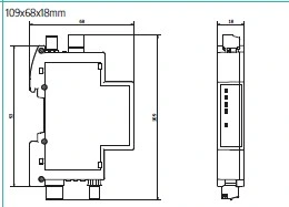
Dimensions
Available Measurements |
||
| Measurement | STANDARD | PLUS |
| IRMS - VRMS - IPK - VPK | ✓ | ✓ |
| Active power (W), reactive power (VAR), apparent power (VA) | ✓ | ✓ |
| Bidirectional energy (kWh), positive and negative | ✓ | ✓ |
| Active and reactive energy (kVARh) | ✓ | ✓ |
| Power factor (inductive/capacitive), crest factor | ✓ | ✓ |
| Frequency | ✓ | ✓ |
| Cosφ | ✓ | ✓ |
| Tanφ per phase and average | ✓ | |
| Average power factor | ✓ | |
| Distortion power factor (inductive/capacitive) | ✓ | |
| THD (V, I), TDD | ✓ | |
| Minimum, average and maximum power | ✓ | |
| Internal temperature [°C] | ✓ | |
| Inverter input (modulated PWM voltage) | ✓ | |
| Time during which active power P is above a set threshold | ✓ | |
| K-factor (according to IEEE Standard 1100-1992) | ✓ |
Communication networks
| Parameter | Value |
| RS485 | |
| Protocol | Modbus RTU |
| Baud rate | 1200÷115200 bps (standard 9600) |
| Addresses | 1÷247 (standard 1) |
| Data format | 1 start bit, 8 data bits, no/odd/even parity (standard no parity) |
| Response delay | 1÷1000 ms |
| Connection | Via removable terminal, T-BUS or micro-USB |
| DIGITAL OUTPUT | |
| Activation | Can be activated via software as an alternative to the RS485 connection |
| Use | Alarm |
| Type | Solid State (MOSFET) |
| Thresholds | <40 V, <100 mA |

Alternative products
These other products may interest you